
Got the boom preventer system all installed this weekend. There are some things that I wish I had anticipated, namely that the lines run right across the cabin top and will require working around when setting or reefing the main sail. I’m not sure that I could have done much to prevent that and still keep a simple system.
After drilling the hole, the next thing that I had to do was install the padeyes that would hold the blocks to turn the boom preventer lines back to the cockpit.
I had already marked out where I wanted the padeyes centered. I ordered some Suncor 1/4″ folding padeyes from defender.com. When I received those, I placed them on the center marks and proceeded to mark the hole locations.
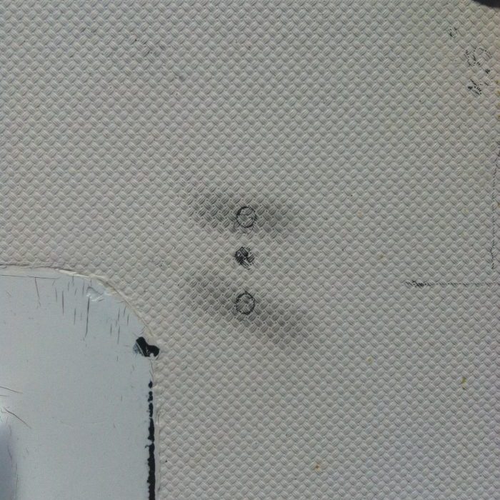
Marks for the padeye holes.
Padeye holes drilled and checking screw fitment.
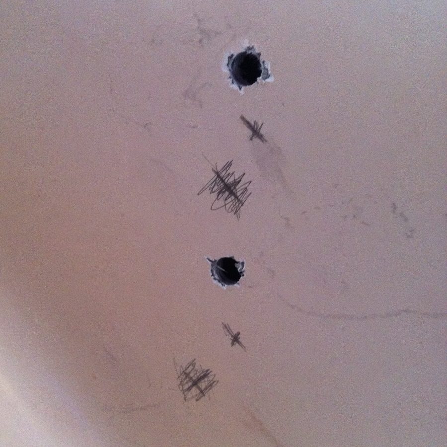
One of the things that I also did when I marked the topside hole locations was try to translate those to the inside cabin top to see where the holes would be. I wanted to make sure that I would have clearance around everything else for both backer plates.
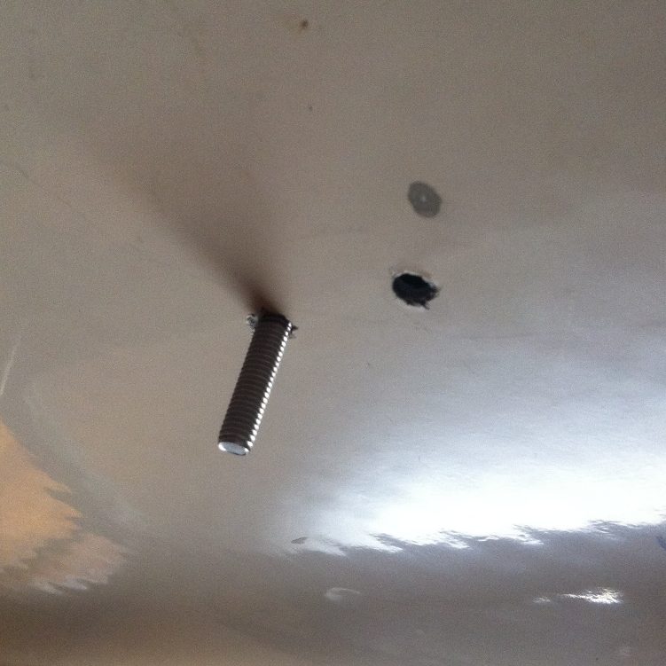
Inside cabin top view of the starboard preventer padeye holes. The pencil circle was my projection of the hole from the top side measurement. Off by about 1/2″.
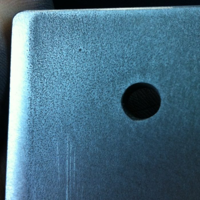
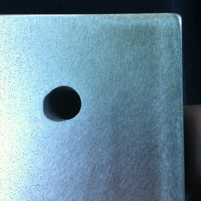
After the holes were drilled, I chamfered them to prevent the gelcoat from cracking once the screws were tightened and also to allow the butyl tape somewhere to spread into to help seal the holes.
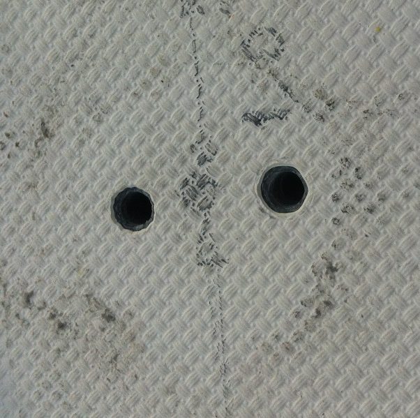
Chamfered holes for padeye
I already had some 1/8″ stainless steel plate that I was going to use for the backer plates for the padeyes. It was just a matter of cutting, drilling, and polishing. Of course, with acorn nuts, I had to cut the length of the screws so that everything would tighten up properly. Everything turned out pretty good.
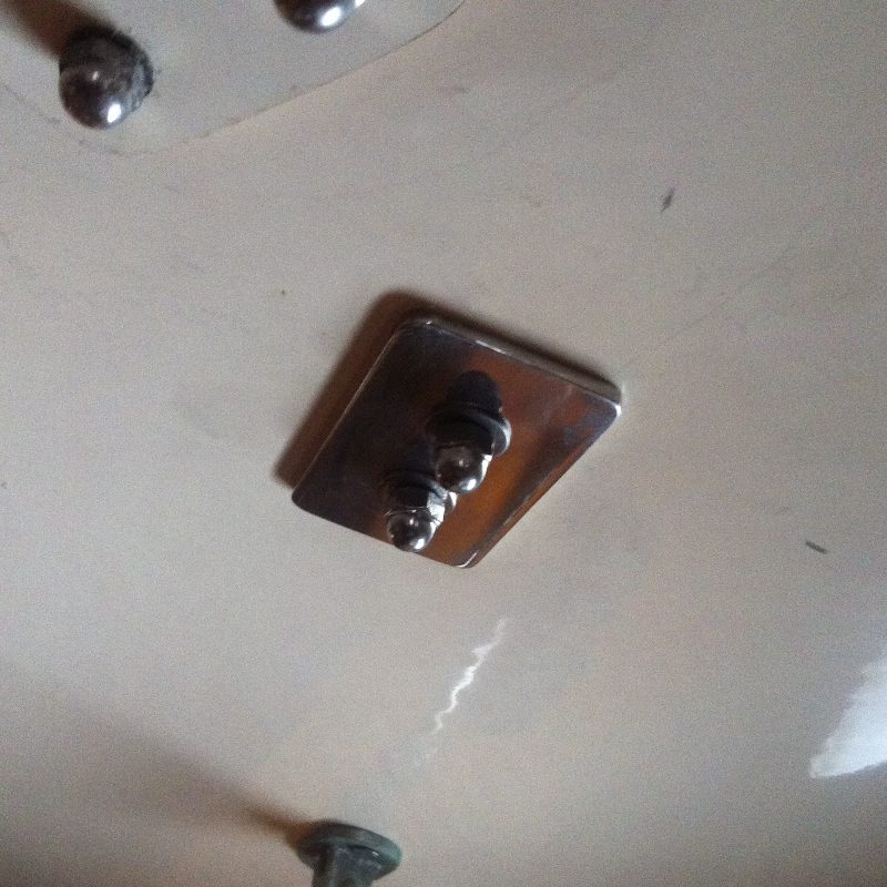
Starboard padeye backer plate
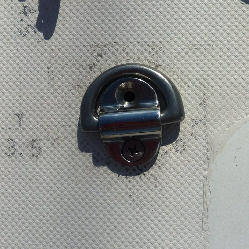
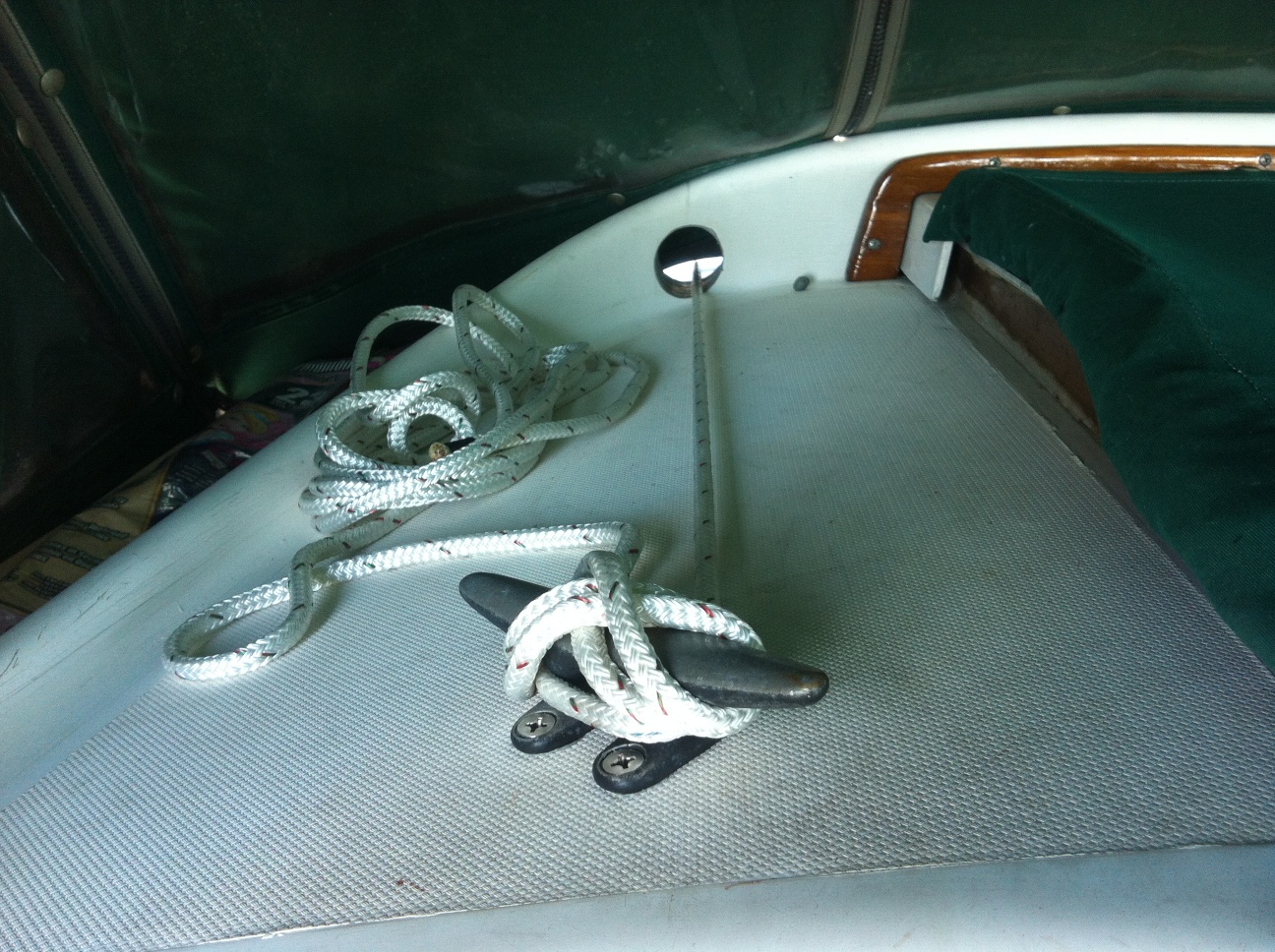
Starboard boom preventer
I purchased some 1/4″ 304 stainless steel plate from speedymetals.com to use as the backer plates for the cleats. I have used these guys for a whole host of metals purchases. There are a number of metal suppliers online that you can order stuff from, but I’ve never had an issue with anything I’ve ordered from them. Of course, I’ve never used anyone else. Maybe I just don’t know what I’m missing. Ignorance is bliss. I’m satisfied and that’s all that matters. Anyway, the plate was 3″ wide by 3.5″ long. I ordered 2.
When I ordered the padeyes, I also got a stainless cleat. The current cleat for the main sheet will be used for the starboard preventer and I needed to install another cleat for the main sheet. I received the stainless plates for the backer plates and proceeded to mark and drill the 1/4″ holes for the bolts.
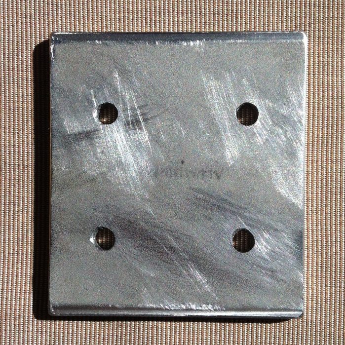
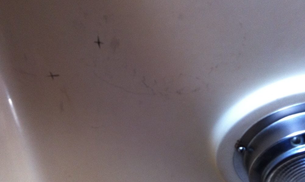
Only one of the backer plates, the port side, would be seen inside the cabin. The starboard plate is tucked up inside the box that holds all the electrical and breaker panel. Fortunately, this meant I only had to clean and polish one of the plates. So, I took the random orbital sander, stuck on a 220 grit disk and went to sanding. The plate had, for lack of a better description, some pitting on it that I had to sand through.
“Pitting”
Pitting almost removed
Once I had satisfactorily removed the pitting, I took a 1500 grit pad and started polishing the plate. All told, this took a couple of hours for one plate.
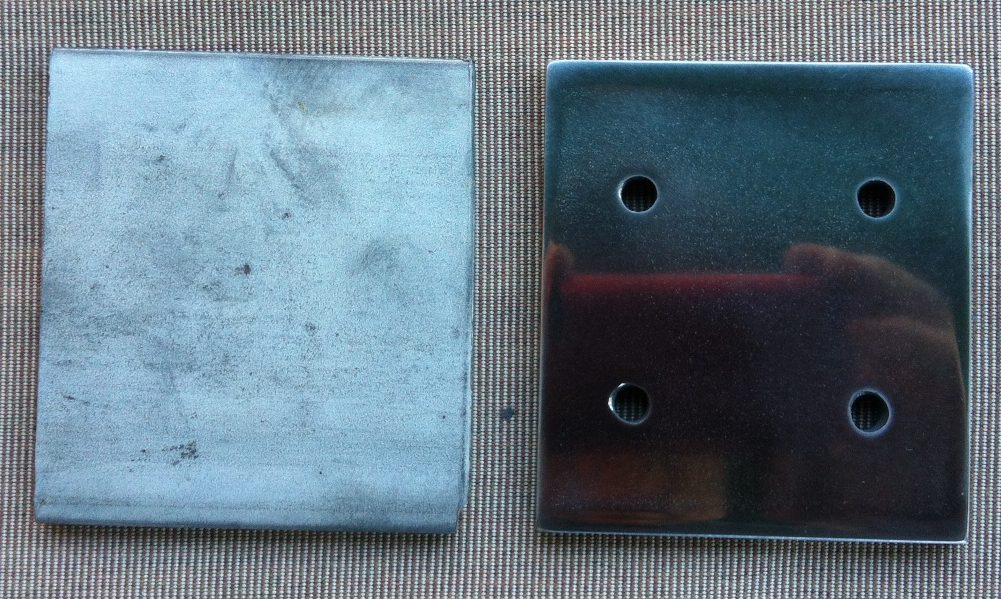
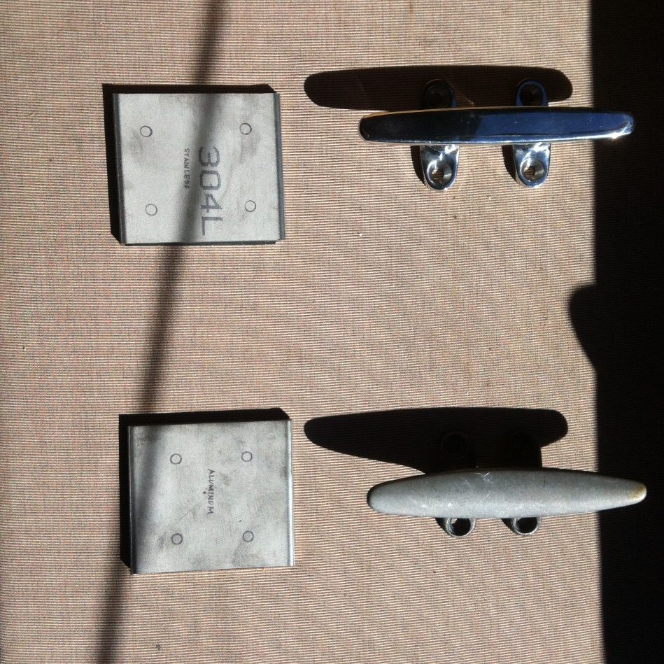
The unpolished plate compared to the polished plate
Now I had to mark and drill the holes on the cabin top for the cleats. I followed the same process that I did for the padeye backer plates. I marked the holes once I had the cleat in the desired placement up top and then translated those inside and checked for backer plate clearance. Here I was a little too close to the curve on the cabin top and had to move forward some.
Initial marks for cleat placement
I moved the cleat and remarked the topside and the inside. I checked the placement of the backer plate and proceeded to drill. The scratched out marks represent my initial placement. The other marks represent my projected hole placement.
Holes off by 1/2″, again, from projected placement
The starboard side didn’t really matter and I couldn’t measure inside the cabinet anyway. I simply placed the cleat, marked, felt inside the cabinet to make sure I wouldn’t hit anything and then drilled. Once all the holes were drilled and chamfered, it was just a matter of applying the butyl tape to the cleats and screws and then installing. As always with those acorn nuts, I had to trim the screws so that everything snugged up properly.
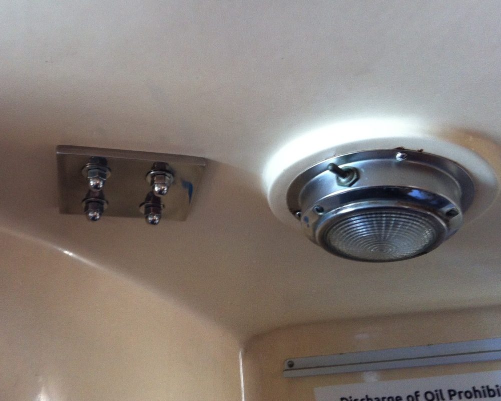
Port backer plate installed
Port side preventer cleat installed
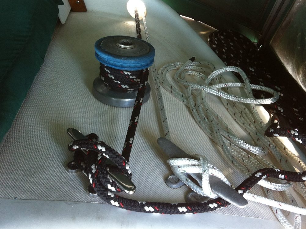
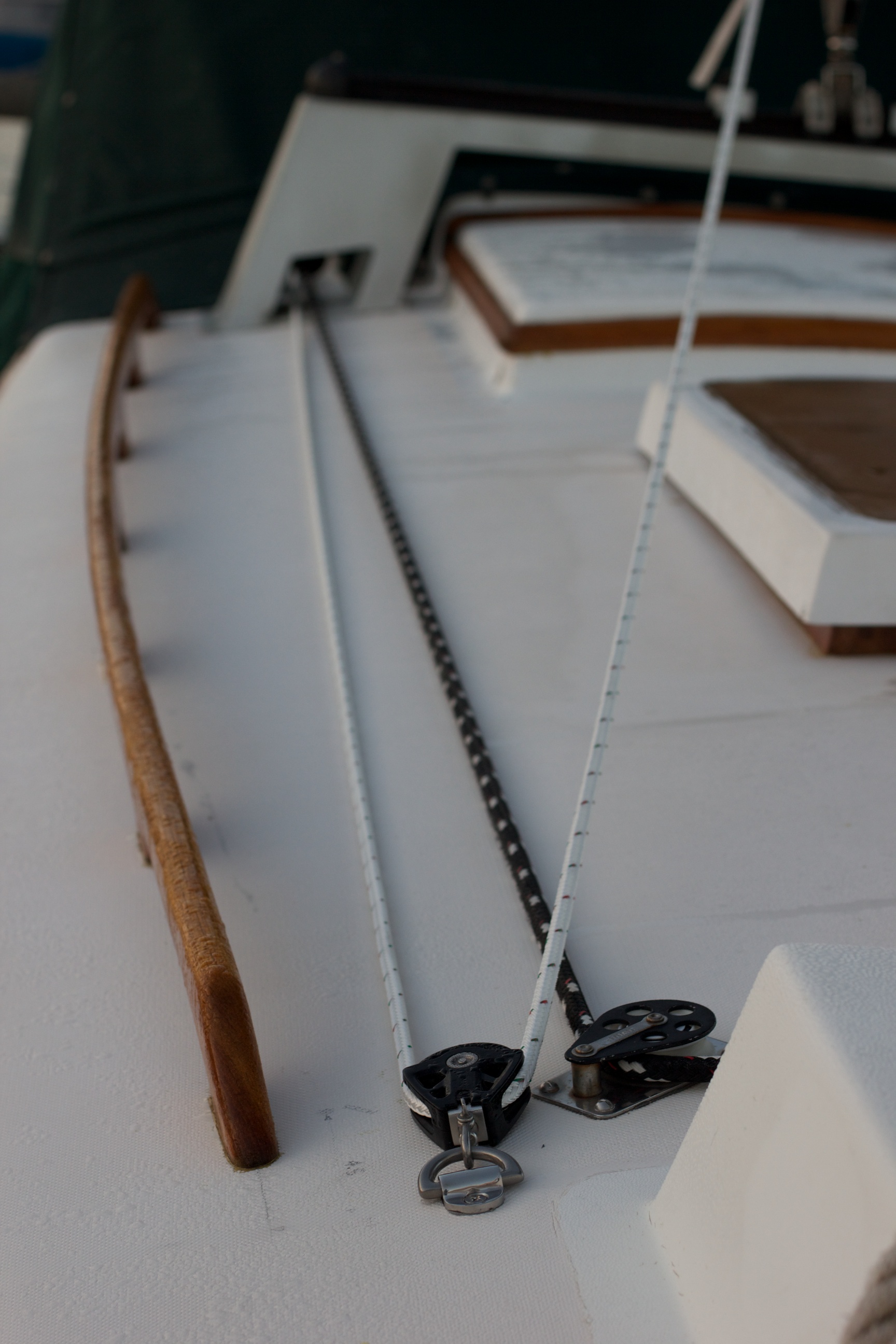
Starboard side setup with main sheet and preventer
Another project finished. If this setup doesn’t quite work the way I would like, I can always add some fairleads in strategic places to redirect lines. It might mean, however, ordering additional line. I got 40′ of 3/8″ Samson LS Yacht braid for each side. This is sufficient line to have the boom swung all the way out as far as Emet’s rear lower shrouds will allow and have 10′ left in the cockpit.
The post makes it seem short and sweet. On the contrary, this took about 3 days of work. Placing, marking, measuring, remeasuring, measuring a third time. Changing location, measuring, marking, measuring, remeasuring. Looking. Thinking. Measuring. Drilling. Wondering how I got the holes off by 1/16″, realizing that I can never get the handheld drill square with the surface that I’m drilling through, and then drilling out a little to allow for everything to fit. Test assembling. Removing. Applying butyl tape. Reassembling. What?!?! It fit when I tested it. Wiggling everything trying to get all 4 screws through the cleat, cabin top, and backer plate. Nerds. That one screw just won’t go. Disassembling. Removing butyl tape. Test assembling again. Reapplying butyl tape. Slowly reassembling everything. Cutting the screws so the acorn nuts snug up. Tightening. Cutting the screws again. Tightening. Cutting again. Tightening. Leaving overnight. Tightening again.
Breathing a sweet sigh when it’s all done and looks good.